|
|
 |
|
 |
 |
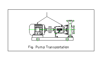
1. Transportation
1-1 In transit, the pumps should remain
level and should be protected from shocks or drops.
1-2 Especially, when wires or ropes
are used for the transport, care should be exercised to prevent
The
damages of accessories such as corks.
1-3 When wires or ropes are used for
the transportaion, the pumps must be moved as shown
|
 |
2.
Installation
2-1 Use concrete to fix the foundation
bolts on a firm ground and then firmly install individual pumps.
2-2 Use the bottom of the joint bed
to perfectly level the ground on which the pump is installed.
2-3 The space should be as large as
possible to facilitate easy access the checking and installed.
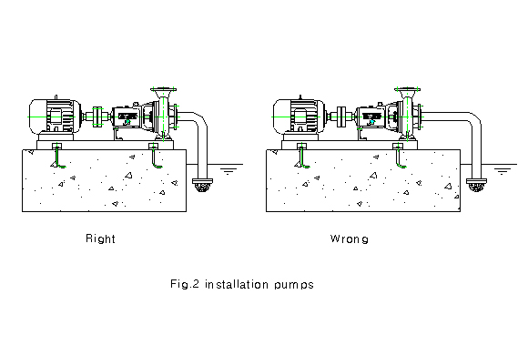
2-4 When the horizontal pump is to be
installed as shown in the Fig. 2 the suction distance should
be
as short be possible.
|
 |
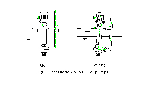
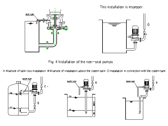
2-5 When the vertical
pump is to be installed, precise perpendicularity and horizontality
must be
established in connecetion with the cistem tank as shown is
the Fig.3
|
 |
2-6 When non-seal pump
is to be installed, it should be installed within the boundary
between the
back of the pump impeller and the central line the overflower
pipe.
|
 |
3.
Piping
3-1 The suction piping should be instslled for each individual
pump and in parallel to one another.
3-2 The suction piping should be as straight and short as possible
and be supported to prevent any
strains on the pump.
3-3 In order to avoid air pocket, the suction pipe should have
the upward slant of 1/50~11/100.
3-4 The piping flanges should be bolted on the same imaginary
line with the pump flanges.
3-5 During the piping work, care should be taken to prevent
any impurities such as welding slags,
bolt, tools and glovers, form entering the pipeline.
3-6 Install the check valve to prevent backward rotation of
the pump during the shutdown caused by
the
backflow of the liquid.
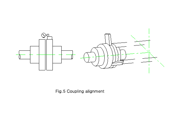
4. Coupling alignment
When the installtion and the pipung
work are completed, align the axis between the pumps and
The motors.
4-1 Loosen the motor securing bolts
and coupling bolts.
4-2 Attach the dial gauge on the outer
diameter of the motor coupling and install the needles at
the
side
of the pump.
4-3 Move the dial gauge so that the
motor axit comes within the up /down and sideway deflection
of
0.05mm. Measurer the coupling clearance with the thickness
gauge at 4 points by the interval
of
degree. aign so that the clearance deviation is less than
0.05mm. secure the motor in place.
|
 |
5.
Preparation for operration
5-1 Cheek the iubrication of the bearing.
5-2 Rotate the coupling with hands to feel any contact of surfacee
inside it.
5-3 Energize the motor and momentatily
turn it on to cheek if it rotates in the same direction with
that of the
pump. (if the direction is reverse, a great damage may be caused
to the pump. Checking the
direction of rotation is very important)
5-4 If the direction of the pump rotation is consistent with
of the pump. Tighten the coupling bolts.
5-5 Check if there are any loose bolts and nuts.
5-6 Fully open the suction valve and completely close the discharge
valve.
5-7 Prime the pump topurge the air.
5-8 If the liquid level is higher then the center of the axis,
open the air discharge cork, suction valve
and the discharge valve to fill the pump.
6. Operation
6-1 Energize and rotate the pump to the normal rate of rotations.(Never
idle run the pump. Make sure
that the suction is underway)
6-2 When the normal rate of rotation is reached, slowly open
the valve until the pressure gauge at the
dischage side reaches the standard pressure, in order to set
the pressure.
6-3 If the pump is run below the standard pressure, the overload
may damage the motor.
The pump must always run at the standard pressure.
6-4 If any failure or defect is found while the pump is running,
immediately shut the pump pff and do
not turn the pump on again until the failure or defect is
removed.
6-5 Running with the discharge valve closed(closed operation)
has an adverse effect on the pump.
Limit the duration of the closed operation .(The liquid level
should be higher than the LOW when
The pump is run this way.)
7. Operatinfg-Stop
7-1 Fully closed the discharge valve and cut the power off
to stop the rotation.
7-2 Cut the supply of various liquids from the external sources(cooling
water, flushing liquid, etc)
7-3 If the pump operation is to be suspended for a prolonged
periond, completely remove the liquid in
the casing by opening the water drain in order to prevent
any damage from the winter freezing.
8. Checks and maintenance
8-1 Checks
1-1 Weekly : leakage at packings and temperature of bearings.
1-2 Monthly : Connection of coupling.
1-3 Quarterly : Lubricating and insertion of one set of packings.
1-4 Yearly : Overall condition of the pump.
8-2 Replacements
2-1 Oil replacement
1) 1st replacement : complete replacement after 100hours of
trial run.
2) 2nd replacement : complete replacement after 300hours of
run since the 1st replacement.
3) From the 2nd replacement, the oil will be replaced at every
800hours of running.
* Re- greasing : first after 100hours of trial run and then
at every 400hours of run.
8-3 Lubrication
|
| Makers |
Oils |
Greases |
| Mobille |
DTE Heavy |
Mobilux Grease - 2 |
| Shell |
Shell Tellus #46 |
Calcium Grease - 2 |
| Caltex |
Regarl & OPE/F |
Multi-Fak Grease - 2 |
| Yukong |
hARMONY #56 |
Crown Grease - 2 |
|
8-4 Packing replacement
1) Remove al the old packings, clean out the inside of the box
and apply the lubricant.
2) Cut the necessary amount of packing so that, when the cut
surface is wrapped around the axis,
Each packing may be aligned in parallel.
3) Insert the packing one at a time and tighten the push bolts
one at a time.
4) Fix the packings so that the cut faces of each packing may
be placed at the right angle.
5) When the packings
are inserted, the center of the lantern ring should meet the
water inlet.
9. Dissembly and assembly
9-1 Dissembly
1) Loosen the coupling
bolts.
2) If necessary,
loosen the power cord of the common bed.
3) Remove the casing
bolts and nuts.(If necessay, remove the oacking push nuts.)
4) Remove the casing,
using the dissembly bolts. Care not to damage the impellers
and axis.
5) Remove the impellers,
sleeves and bearings from the axis, without applying too mucttorque.
6) Place the removed
parts inan orderly mannaron a cloth or paper, which is laid
on a clean surface
In
order oder to prevent any confusion when the pump is put together
again.
|
| Troubles |
Causes |
Troubleshootion |
| Water does
not run. |
Suction pipe or the strainer
clogged |
Clean out them. |
| Air in the suction. |
Check and repair the suction
pipe system. |
| Revers rotation. |
Change the wiring. |
The stroke
and the discharge
Do not reach the standards. |
Minor air inducement. |
Check and repair the suction
Pipe system. |
| Cavitation. |
Replace the suction pipe
(minimizing the loss) or lowerthe location of the pump. |
| Wear and clogging of the impeller. |
Clean or replace the impeller. |
| Slow rotqations. |
Check and repair the motor and
The power |
| Damaged discharge pipe. |
Check and repair the discharge
Piping. |
Pump check point different from
The actual stoke and flow. |
Check and repair the discharge
Pipe system. Replace the pump. |
| When initial
water dischargeIs quickly followedby no waterflow |
Air pocket in the suction pipe. |
Repair the suction pipe. |
| Air influx. |
Check and repair the suction pipe
And the packing. |
| Low water level(suction stroke) |
Low the position of the pupm. |
| Overload |
Poor alignment. |
Re-align the system. |
| Excessive discharge. |
Close the discharge valve to
The pump |
| Bended axis. |
Replace the axis. |
| Impurities in the impeller. |
Dismantle and clean the impeller. |
| Bearing overheated. |
Improper type of iubricant or
Lack of lubrication. |
Replace and refill the lubricant. |
Defective bearings or poor
Bearing assembly. |
Replace and re-assemble the
bearing. |
| Poor alignment. |
Re-align the system. |
| Poor impeller balance. |
Correct or replace the impeller. |
| Severe pump
vibration. |
Poor alignment. |
Re-align the system. |
| Poor installation. |
Correct the installation. |
| High discharge. |
Close the discharge valve. |
| Poor impeller balance. |
Correct or replace the impeller. |
| Curved axis. |
Replace the axis. |
|
| |
| |
| |
|
|